Table of Contents
What is it?
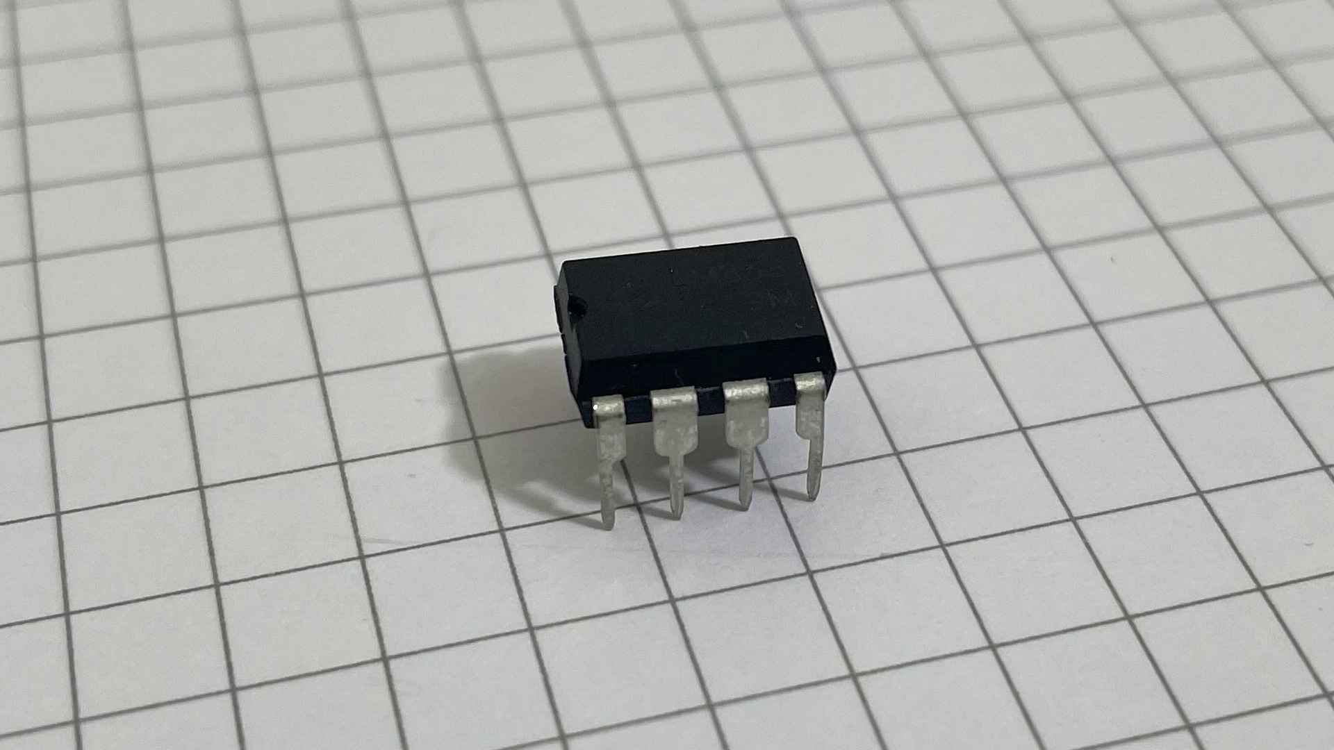
The LM358 is a 8 pin IC with 2 Op-Amps in it. It is a very popular go-to solution for a lot of situations.
I always have a couple of those lying around just in case.
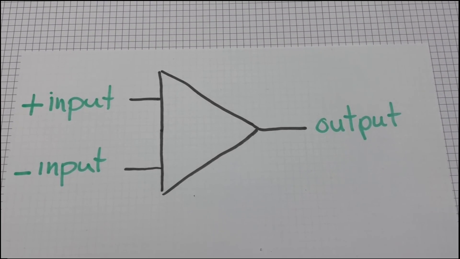
An Op-Amp is a circuit that has 2 inputs and 1 output. And that output changes based on what the 2 inputs are seeing.
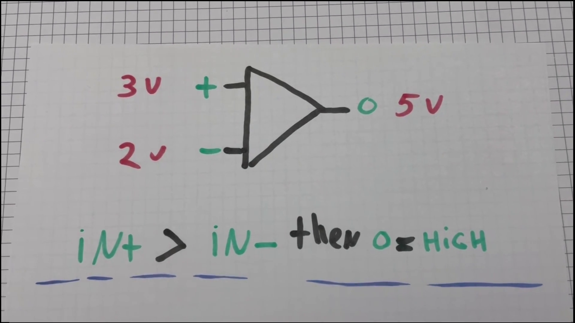
A generic Op-Amp, which this is, follows the following conditions.
- When the voltage on the positive input is higher than the voltage on the negative input, the output goes high
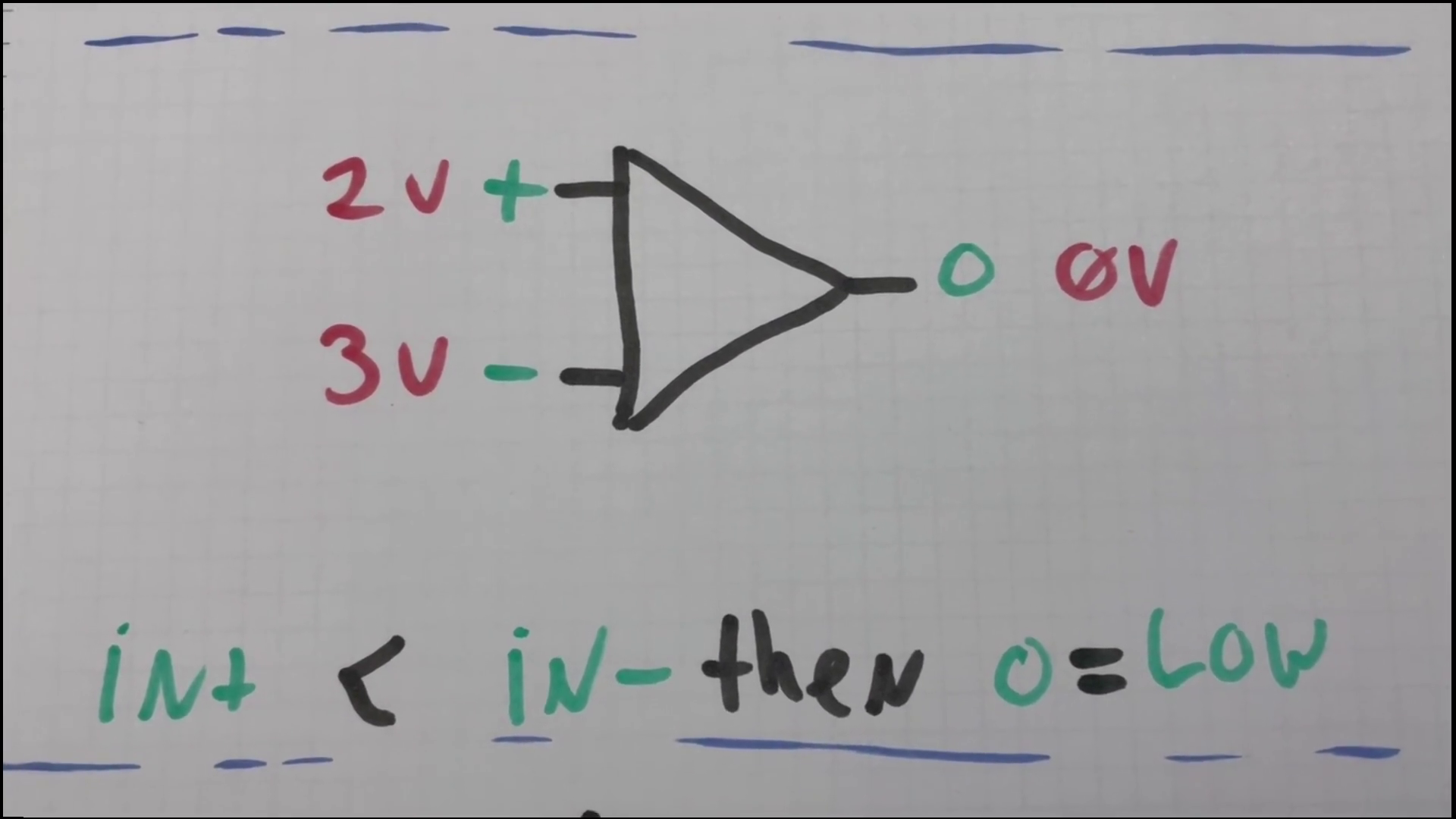
- When the voltage on the positive input is lower than the voltage on the negative input, the output goes low
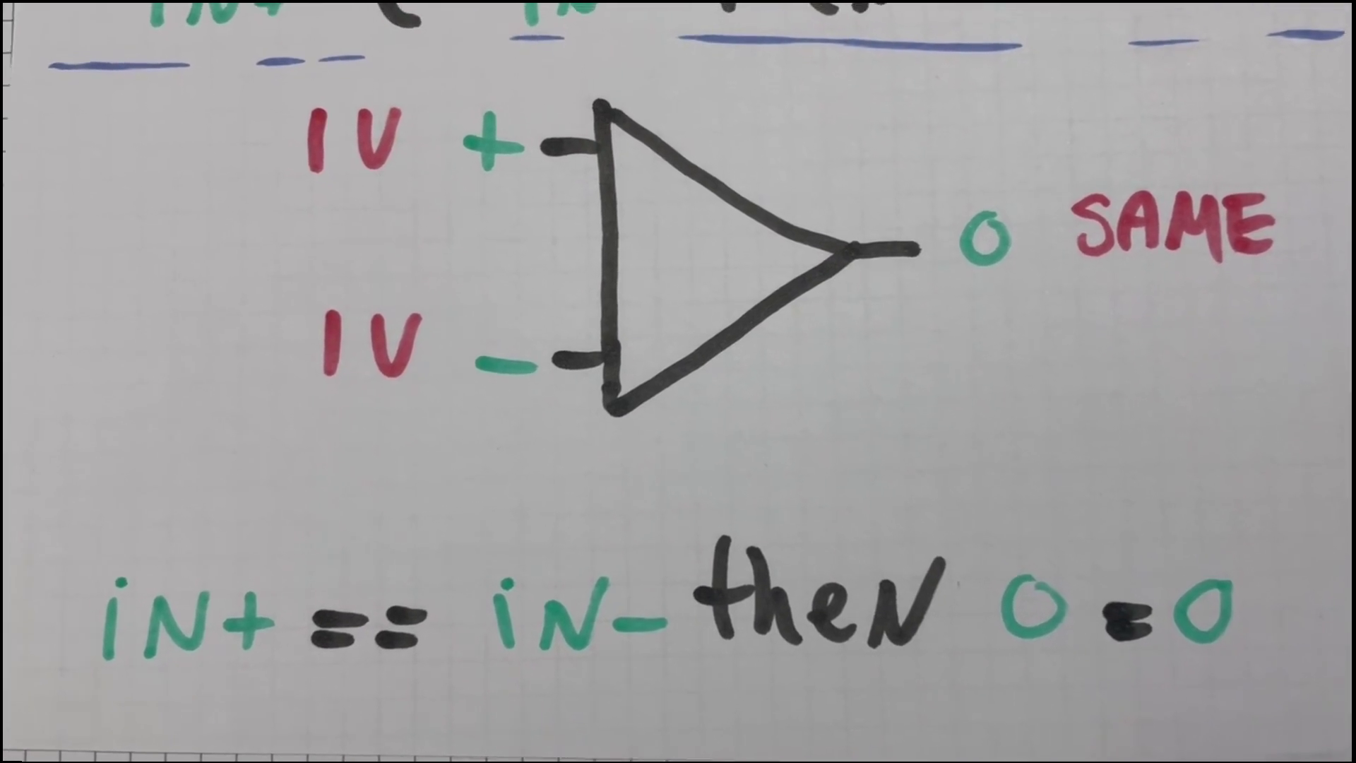
- When the voltage on the positive input is equal to the voltage on the negative input, the output remains the same
What can it do?
Amplifier
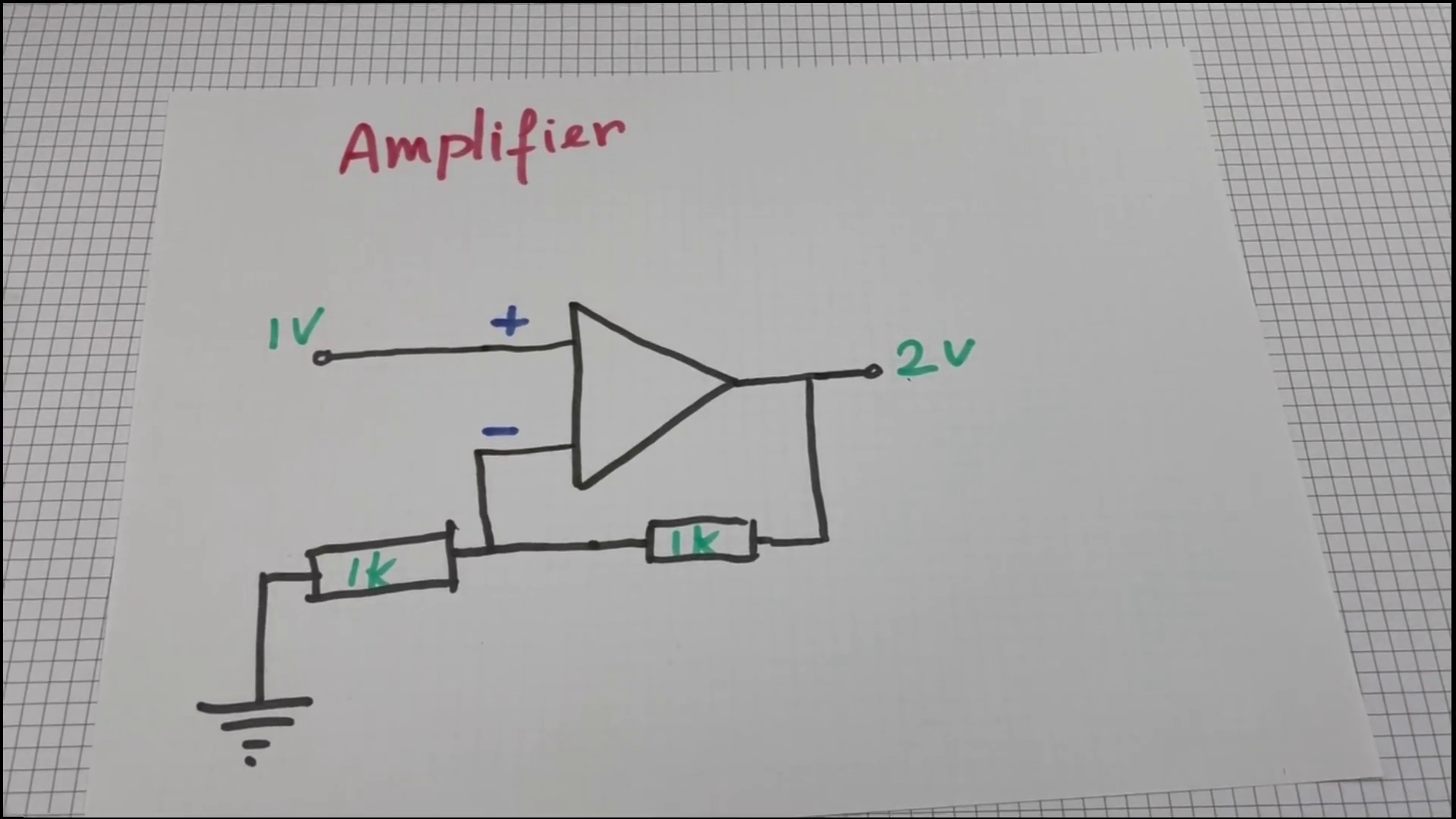
We can use a single Op-Amp to amplify a signal by a certain amount.
PWM
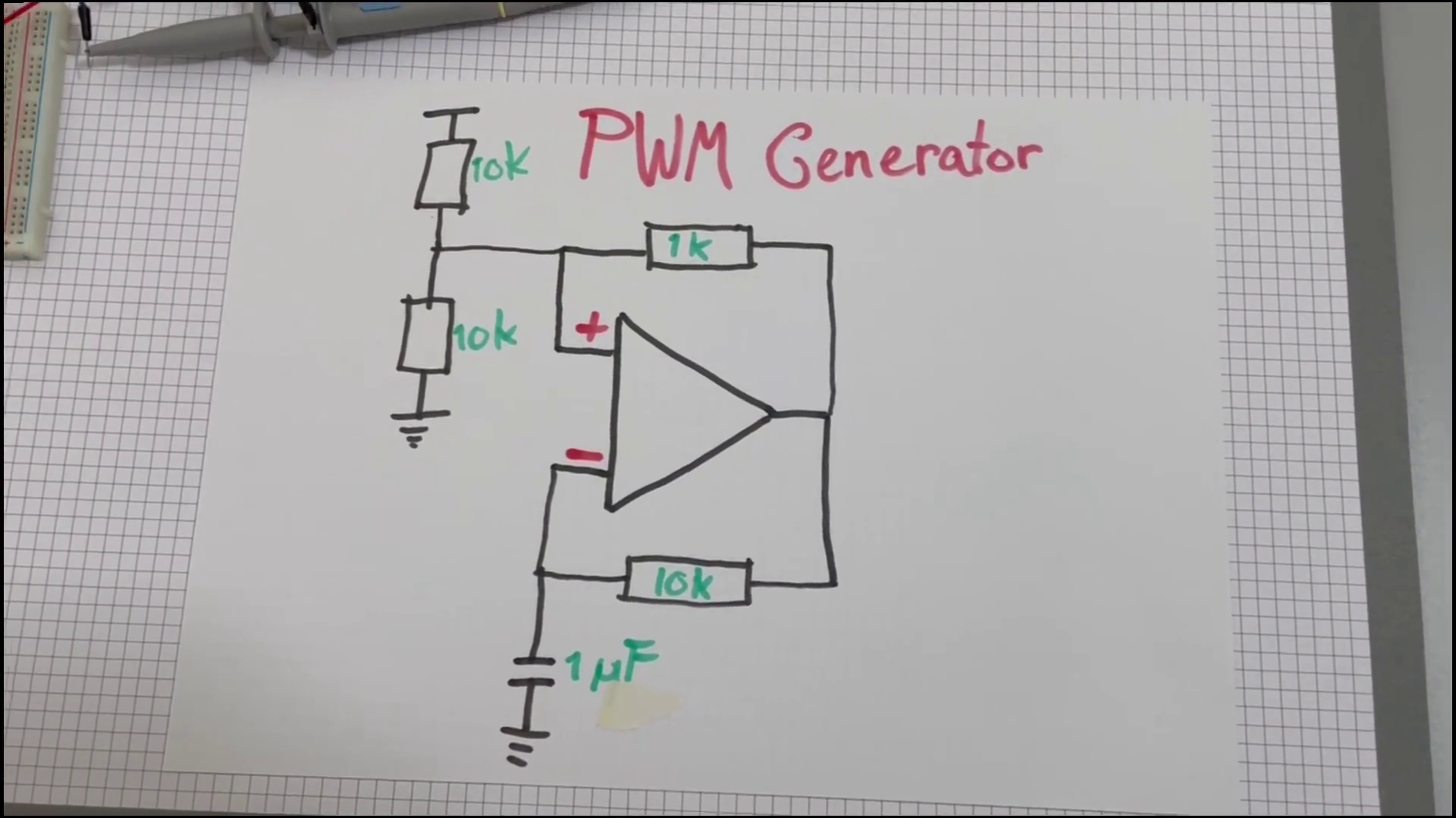
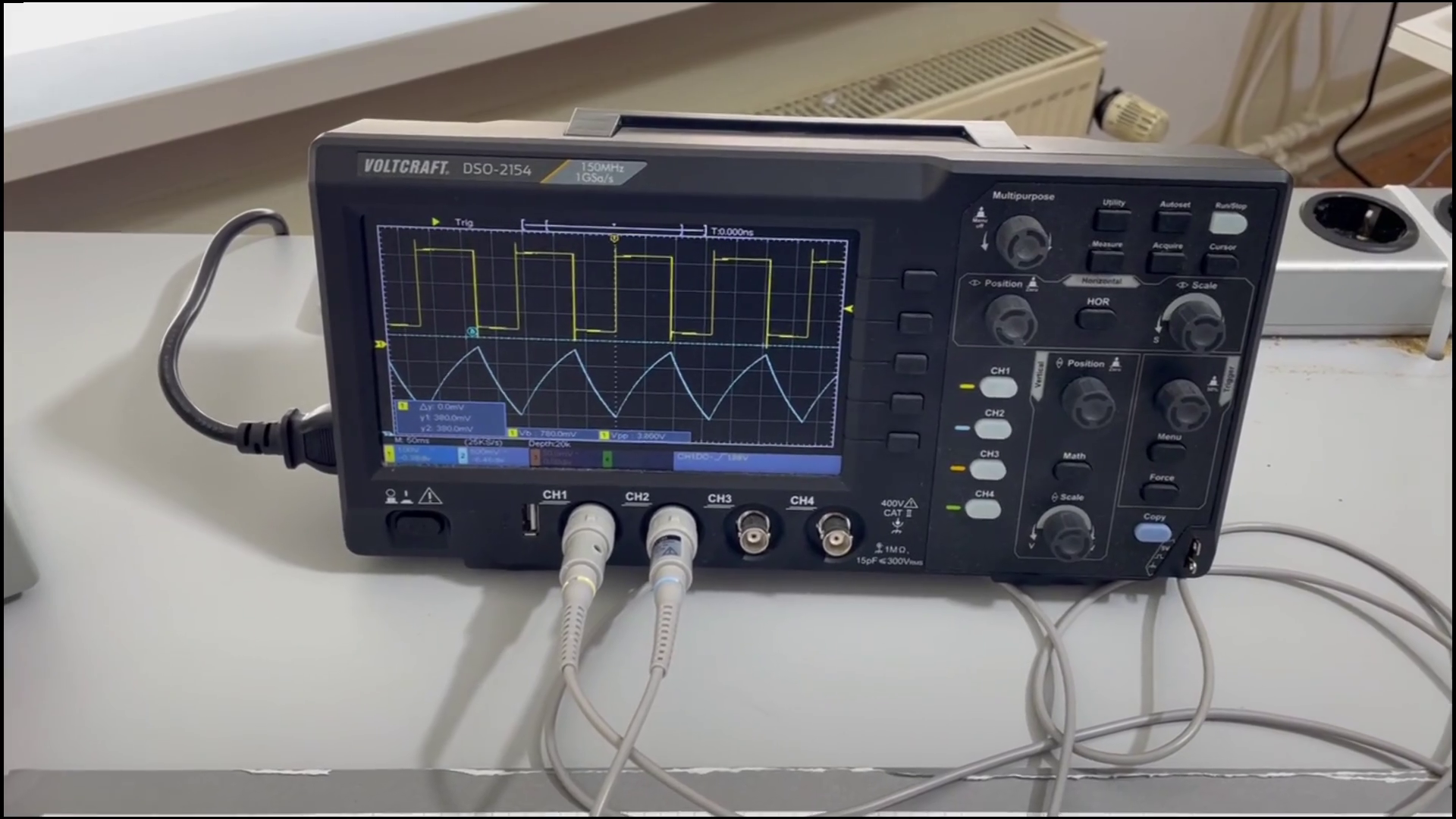
We can have it make a square wave signal, and even make it do PWM if we use the second Op-Amp from the IC.
Logic signal inverter
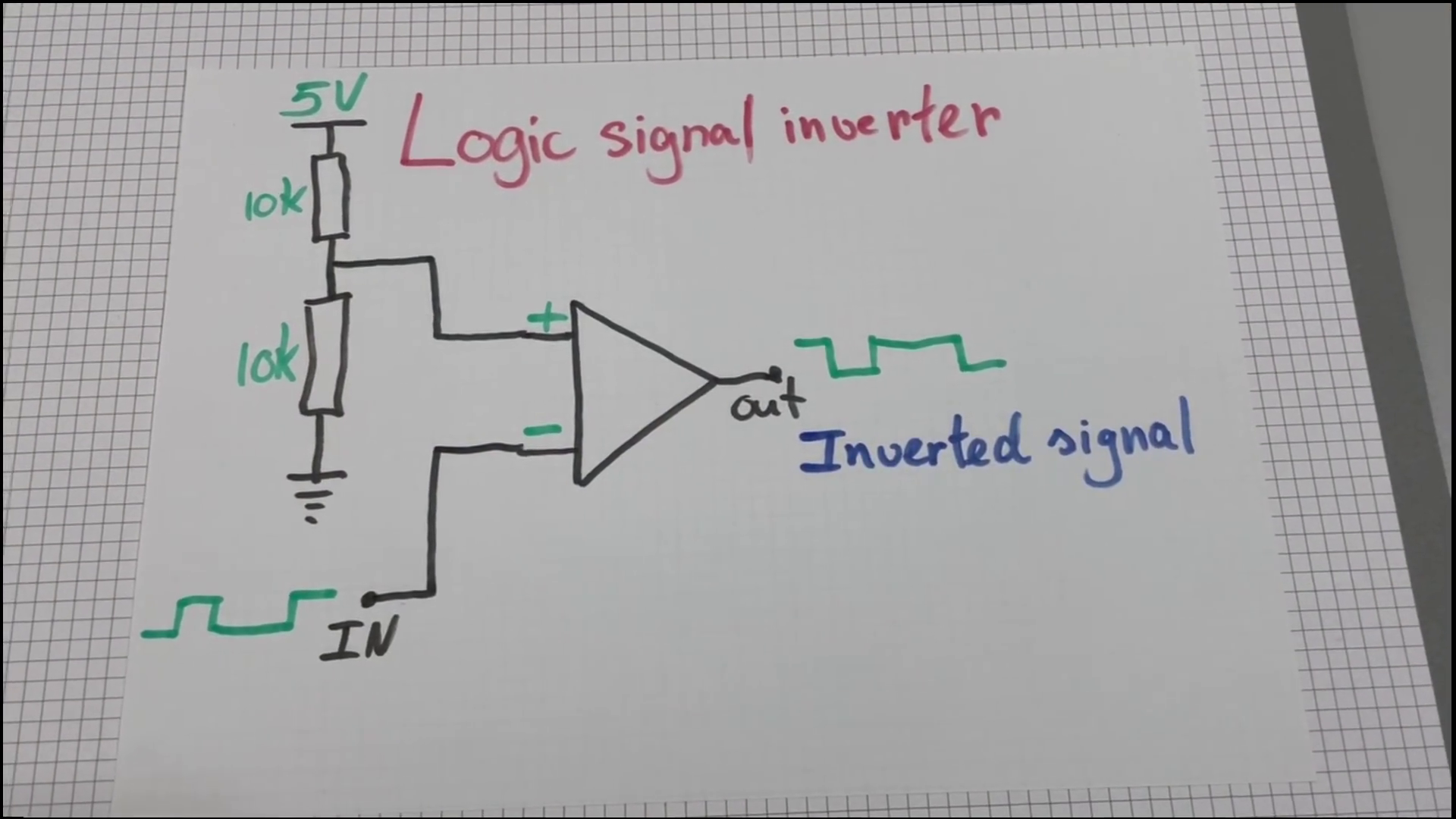
Turn a digital 0 into a 1 and vice-versa.
Logic level converter
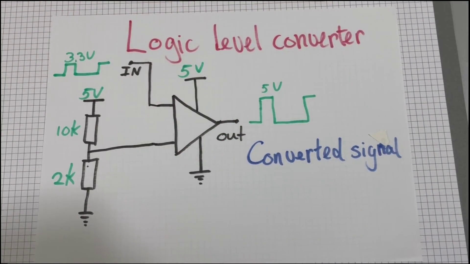
Make a digital 5 volt signal into a 3.3 volt signal. Or the other way around.
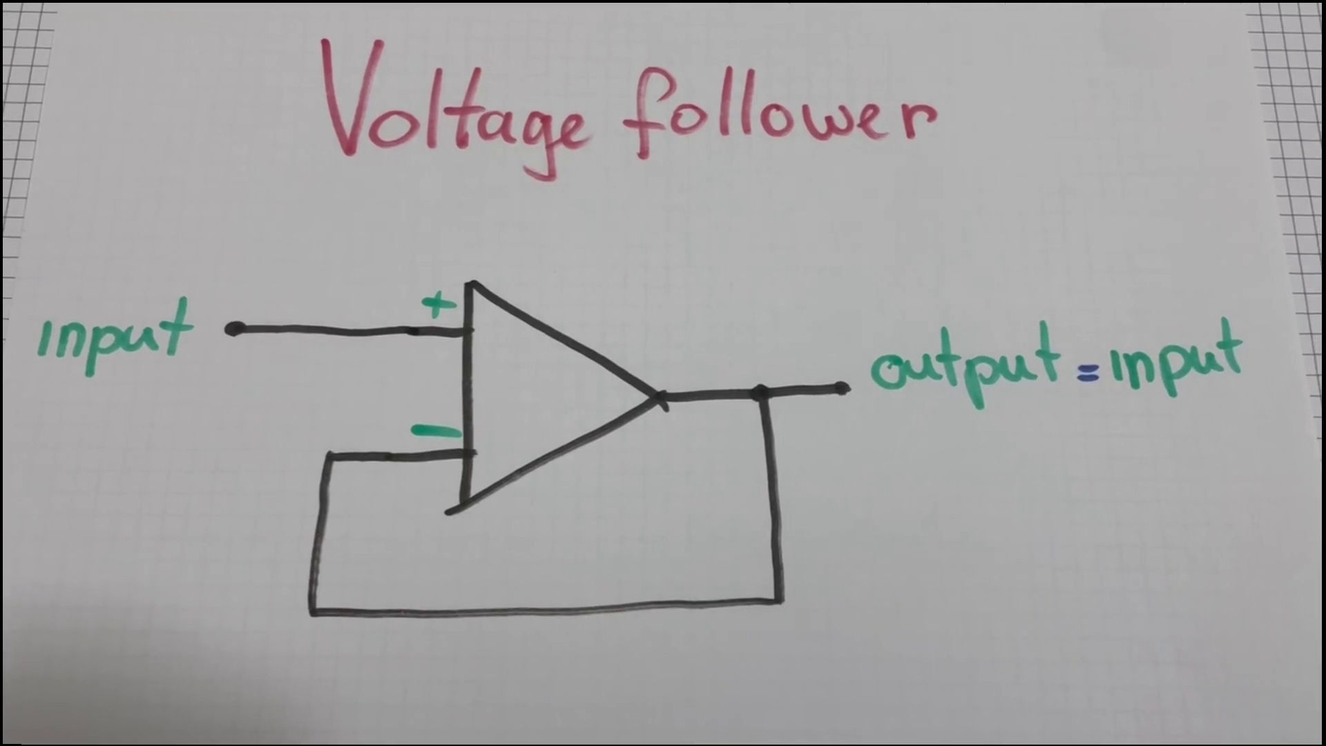
Voltage follower
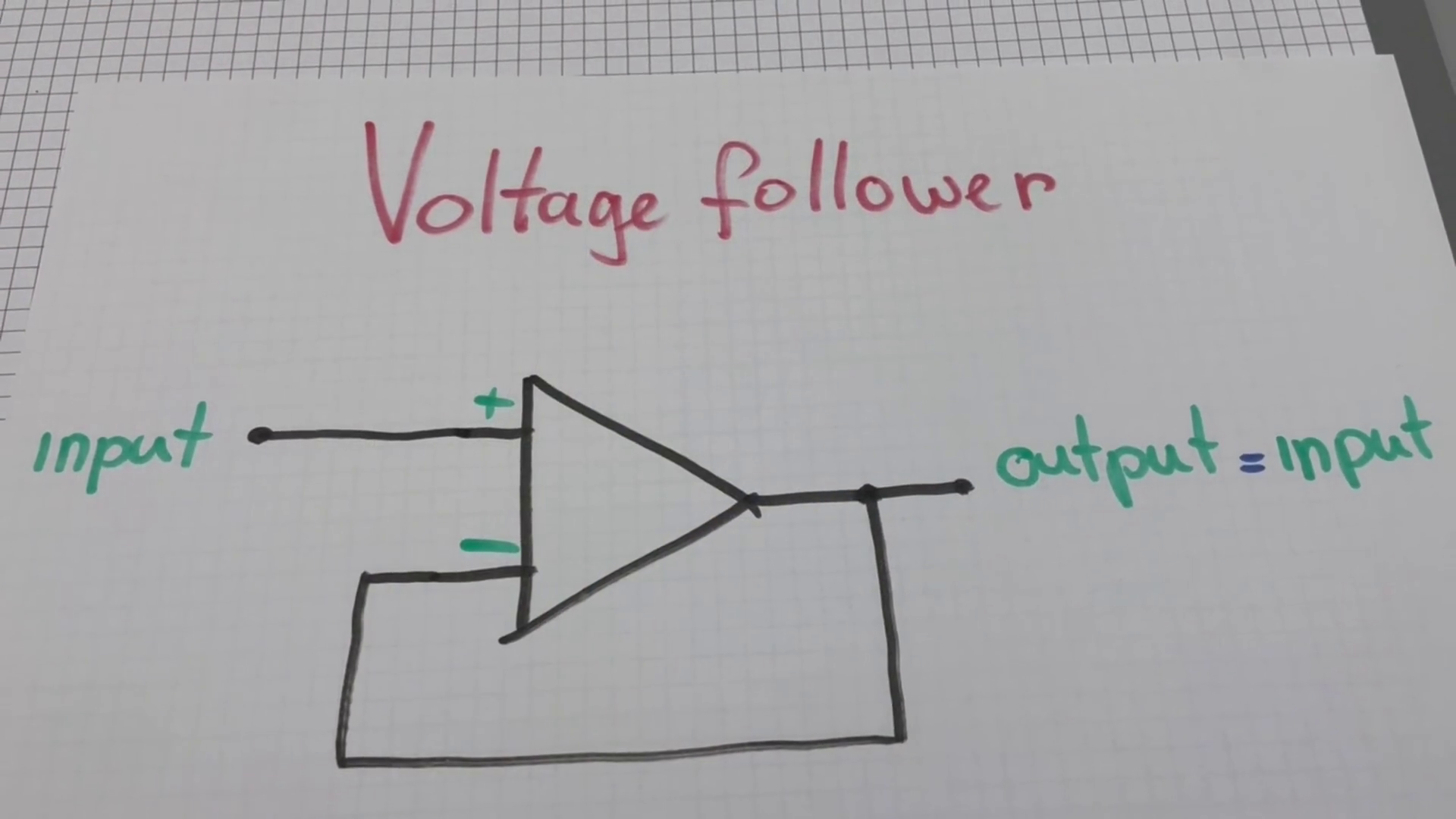
This one is rather boring but also very useful. It lets us drive other circuits without disturbing the input signal.
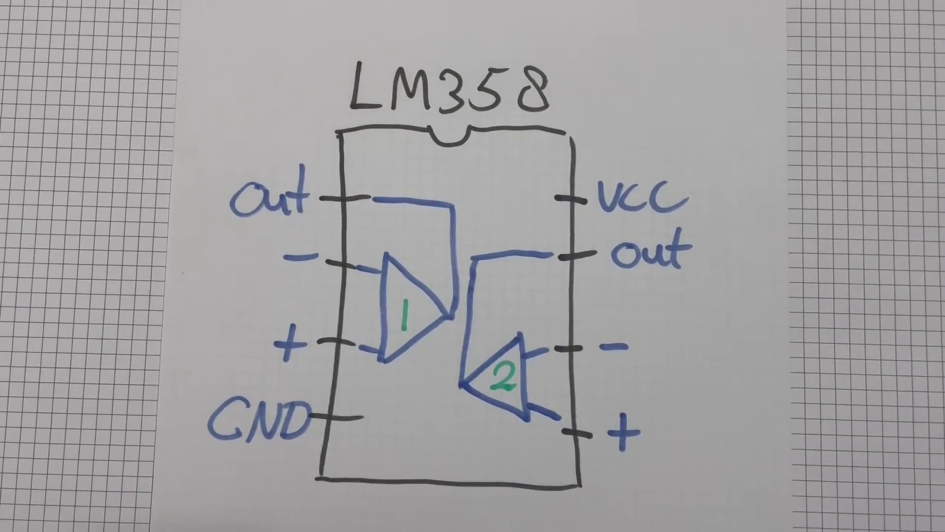
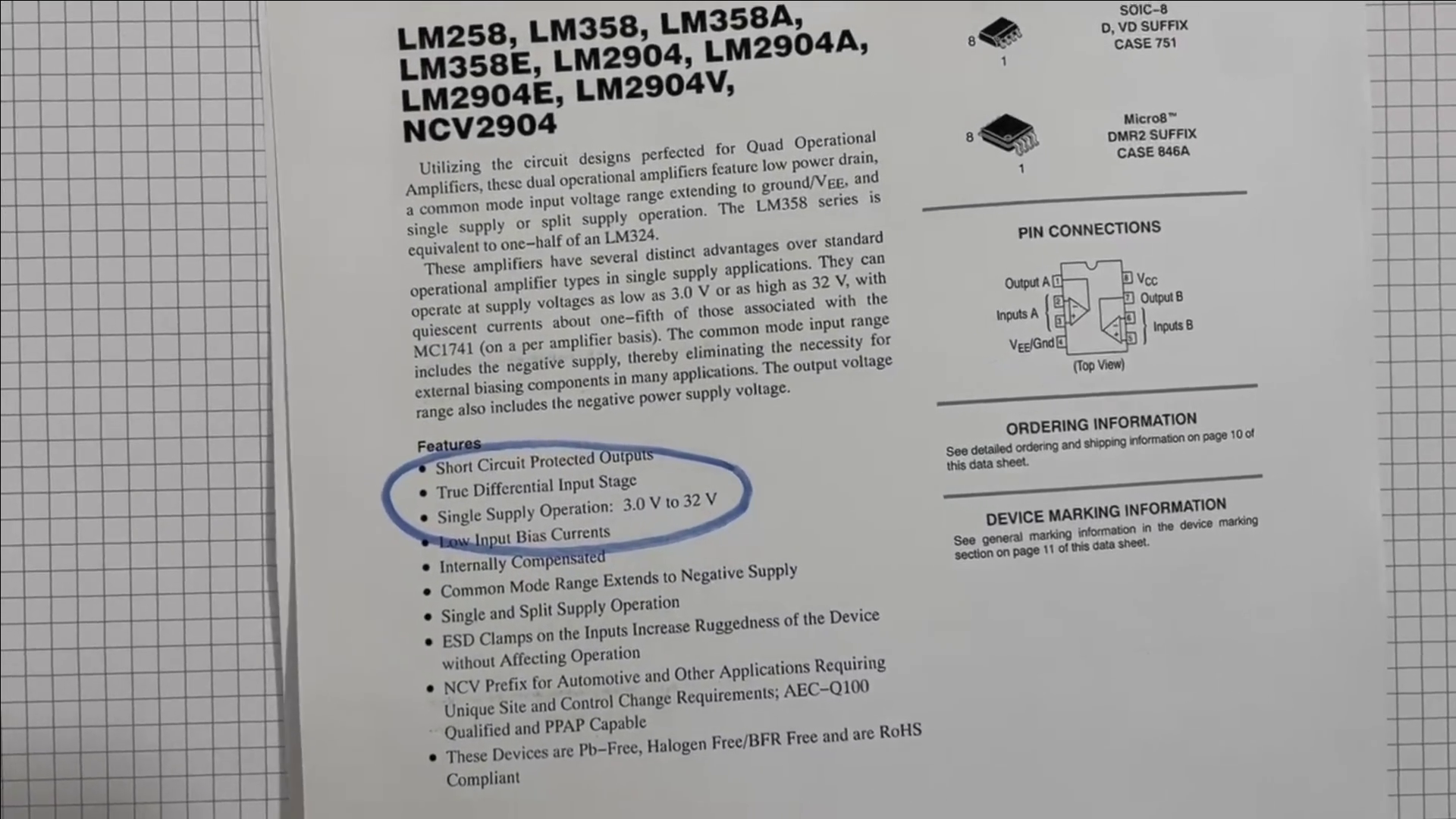
Pin-out
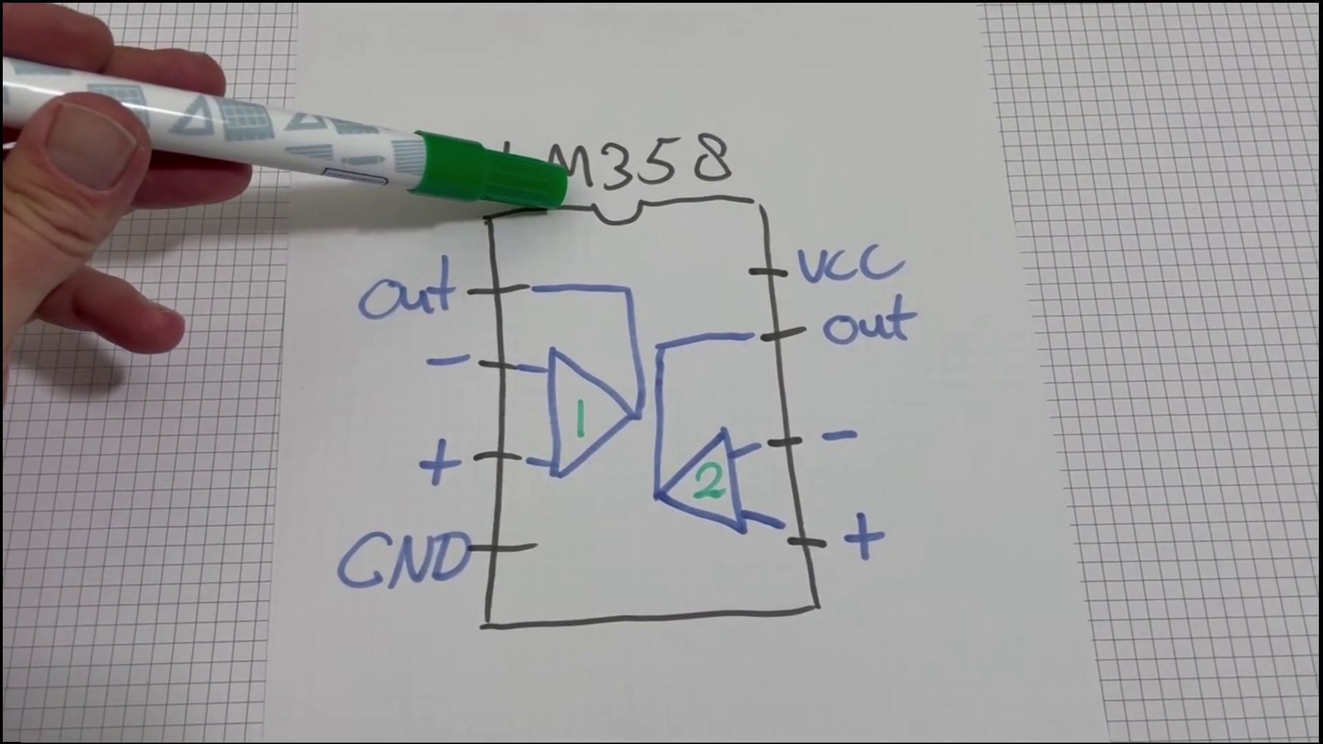
The notch here shows us what side is north on the IC.
Both Op-Amps are powered from a single power-pin on the top-right, and a ground-pin on the bottom-left.
The first Op-Amp then has its connections on the left-side and the second one on the right-side.
I always keep a drawing like this on the table when building a circuit.
Datasheet
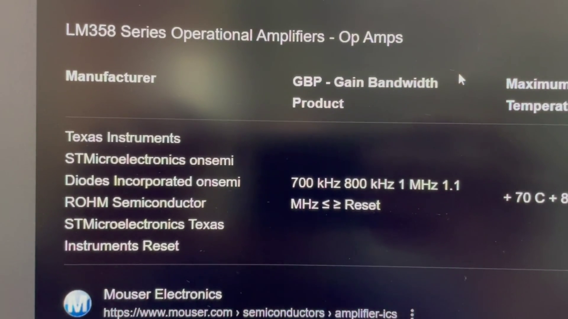
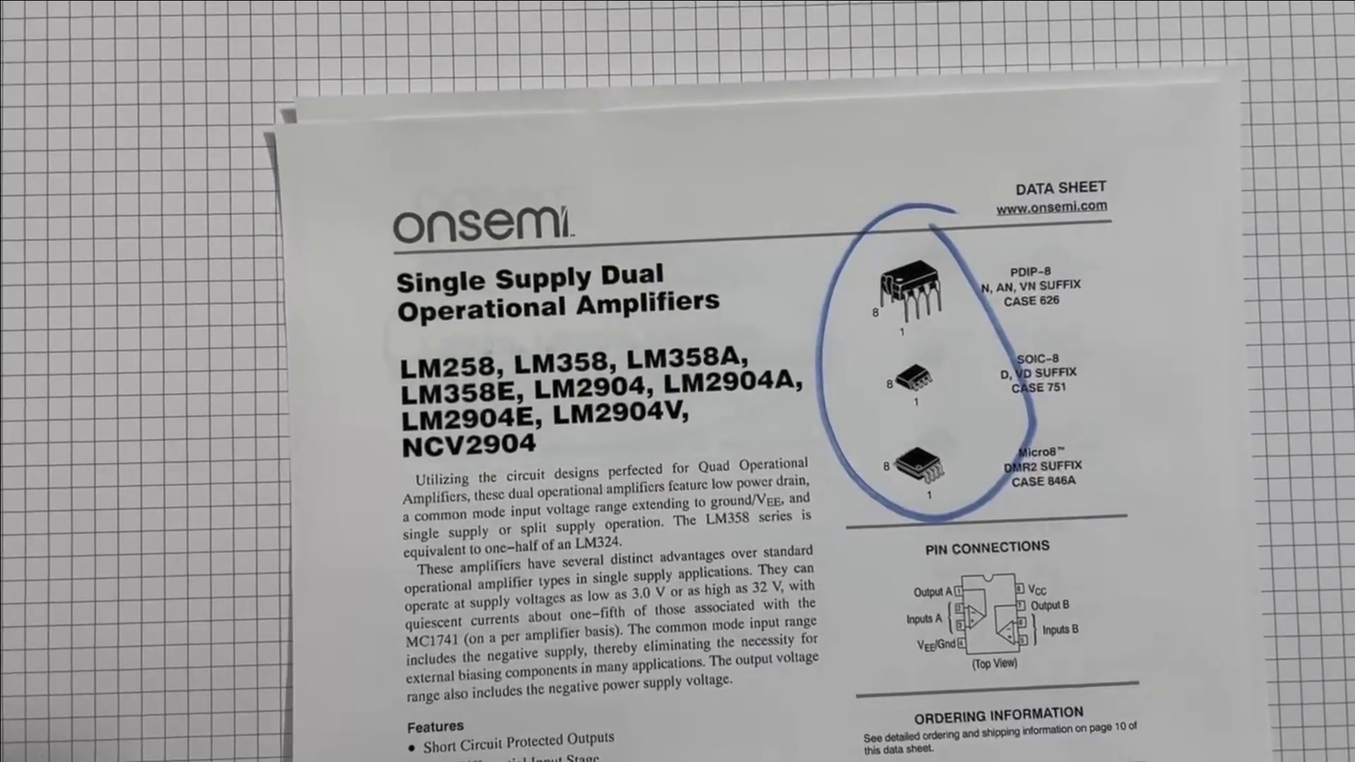
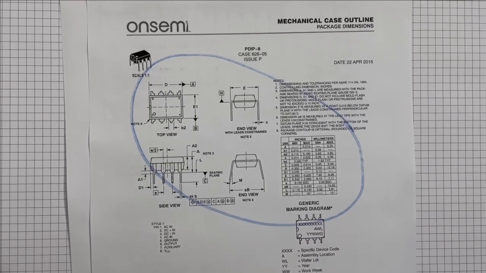
This IC is made by many manufacturers and most of them also have a datasheet for them.
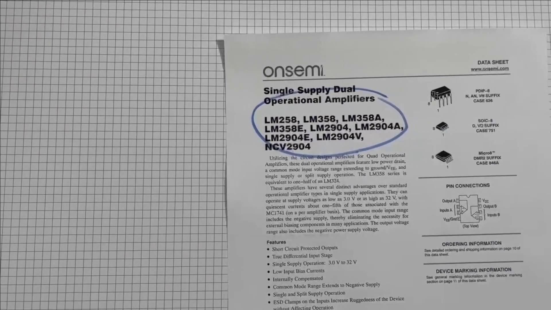
We can find some useful information here like:
- A list of similar devices, looking for a IC with 4 Op-Amps? It in this list
- The different IC “packages” as they are called, There are also SMD variants for example
- The voltage range it can handle. So you don’t burn the IC on accident
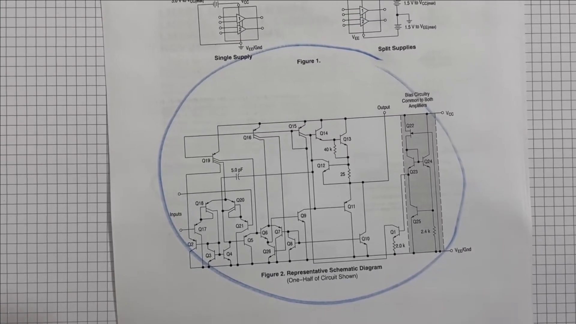
- A schematic of the inside
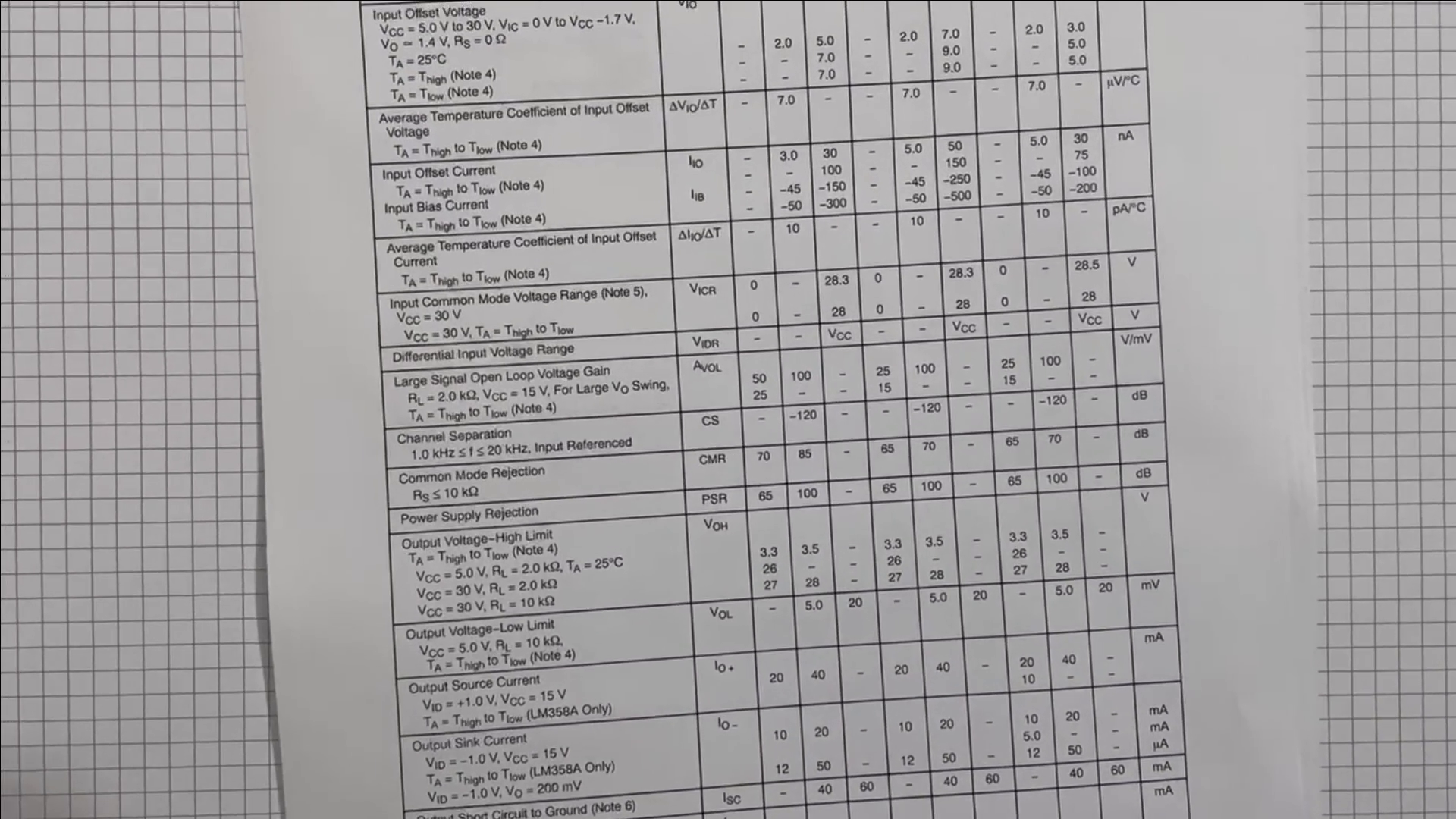
- A long list of highly-specific numbers, you will know when you need to look here.
- Measurements of the IC, in case you are building a circuit-board of your own
How to connect
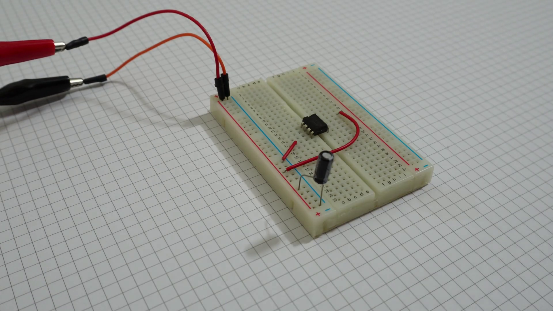
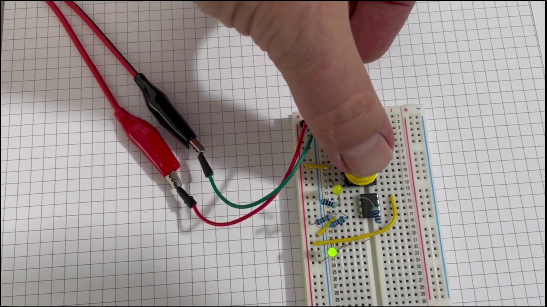
Lets get this thing on the breadboard.
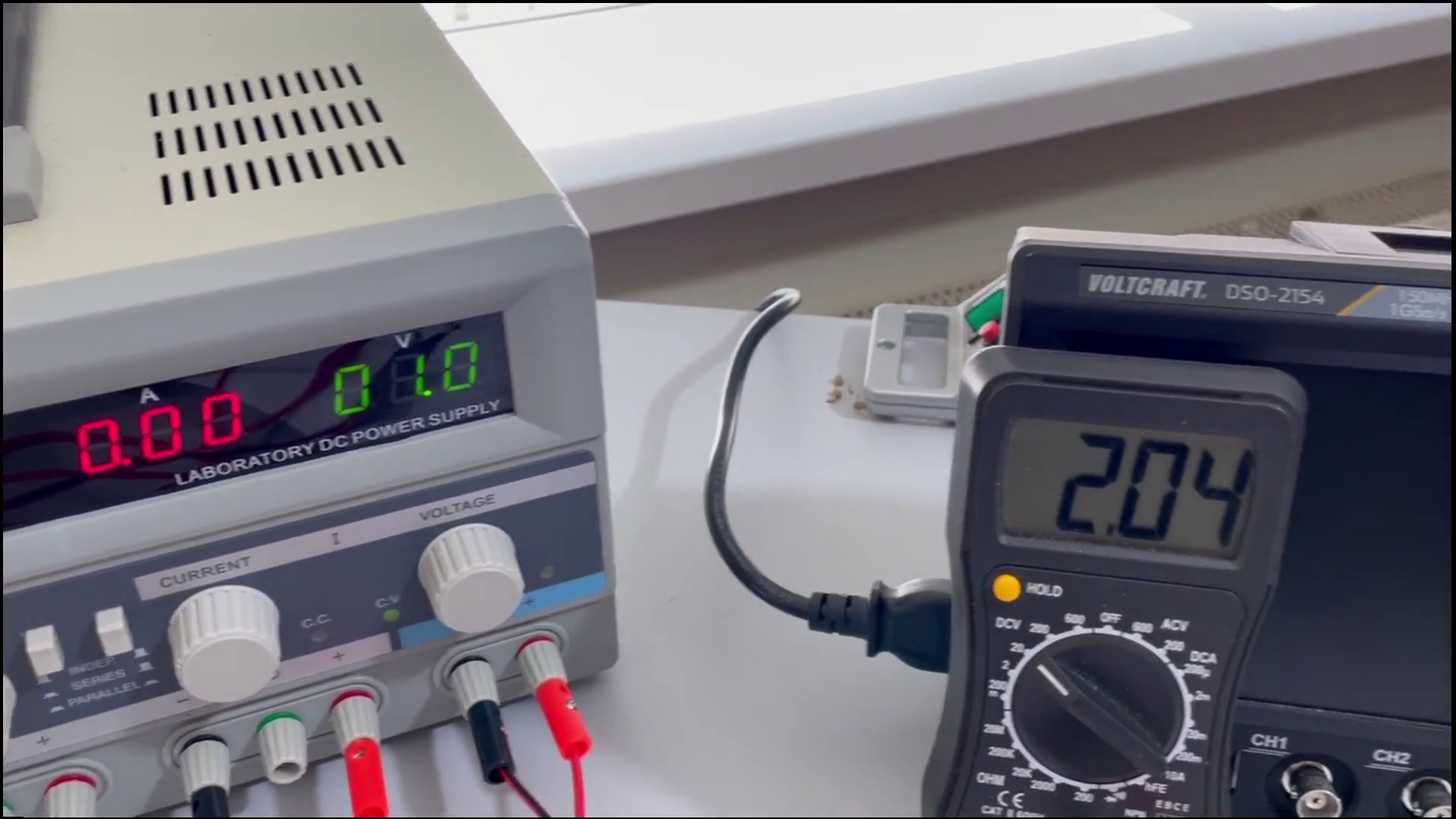
Now connect the power-supply to the top-right and bottom-left pins.
And adding a capacitor over the power supply is always a good idea to prevent problems.
How to test
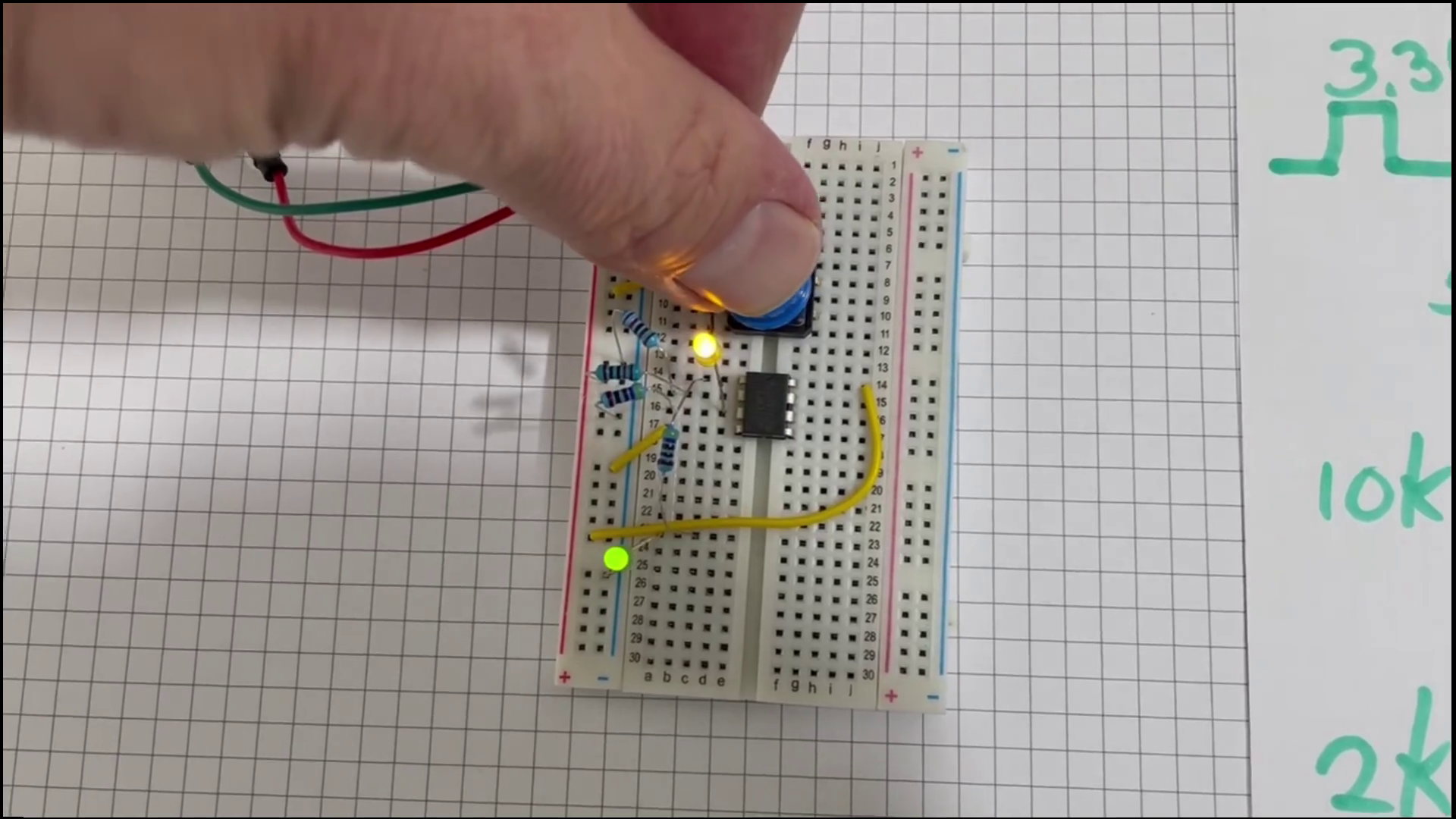
I add an LED to the output. So I can see what it is are doing.
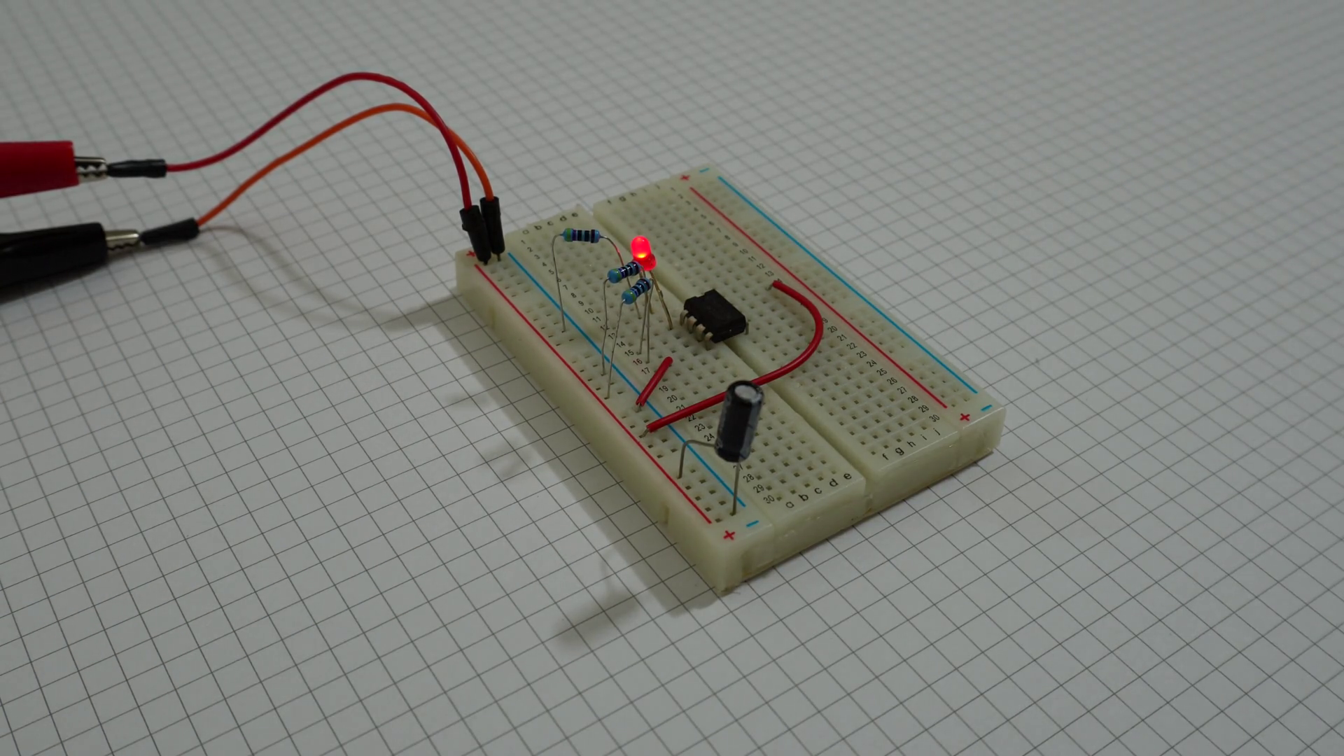
Test case one: Positive input greater than the negative. Output is high so success!
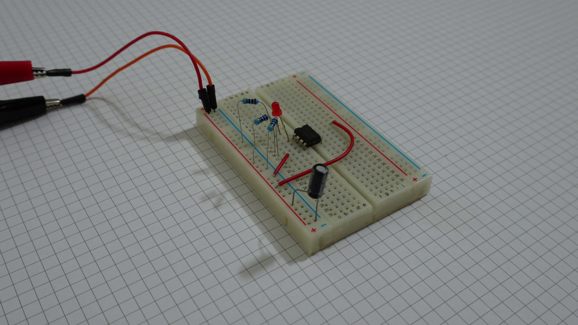
Test case two: Positive input lower than the negative. Output is low so also success!
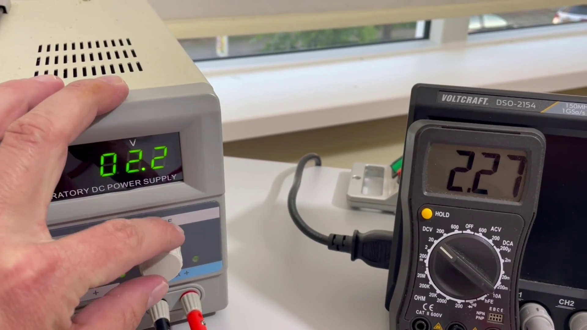
Test case three: Equal inputs. This will need a bit more explanation before testing.
If I were to tie the both inputs together to the same voltage the output would go either high or low, because there will always be a very small voltage difference.
The only way to test this properly is to have the output be connected to the negative input.
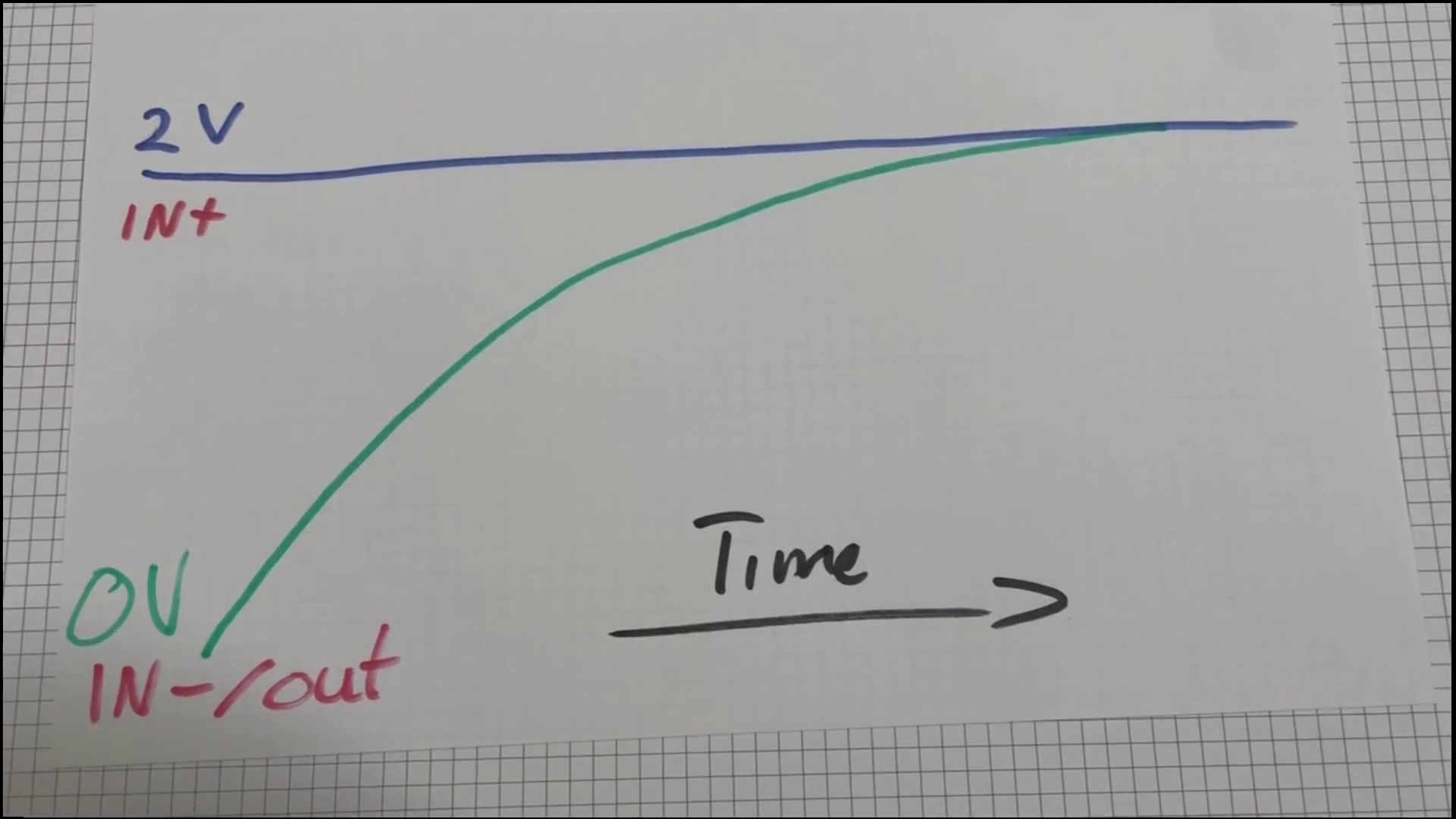
It will then stabilize like in this figure.
Voltage will either rise or fall initially, depending on what the output is at first and then stops when the inputs are equal.
This last thing will not happen if the IC is not an Op-Amp but a comparator. The more you know!
Thank you for reading!
Leave a Reply